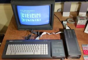
Multiple drives on CPC 6128

As it’s not really needed to have mutiple drives at this time since everything that has ever released for Amstrad can be fit into one single USB, it’s really fun having multiple drive, and I’m not talking about just two, but more of them.
Issue with one drive model
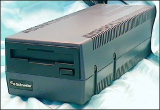
Seems like Amstrad did actually planned to have external drive, like FD-1 for various purposes like not needing to swap disks, to have larger storage, or maybe on 464 to actually have one external disk drive.
However, in some cases some application will not work correctly as they would require only A drive to be available for reading data, and as most user have only A, it will refuse to use B simply because it’s hardcoded that way.
To solve this problem what you can to if you already have one internal drive, you can make a switch called ABBA switch which basically swap A,B to B,A drive and secondary drive will become first one while first one will become secondary. More on this later on.
How Amstrad made switching of drives
Well, what would you actually expect here is something similar to what PC has done – to have independent 4 lines to selecting 4 drives. There this is simply done by twisting the cable that is selecting drives so drive will respond to new signal.
In theory this works just fine – you need to attach particular drive to straight cable to be “A” or to twisted cable to be “B” and basically that’s it. As far as I know no way for other drives to be available this way, but signals are there waiting.
In case of Amstrad situation is a bit different…
Now, instead of two signals which can be high and low, we have only one signal which can be high and low. So output from FDC (Floppy Disk Controller) chip is deciding which drive is selected by sending high or low signal. Interesting thing is that FDC chip is having 2 outputs, not one, but second output is not used at all (not connected to board and lines), so while there is potential it is unused. Also remember here that we would need not just FDC connections but also support in ROM which is non-existing.
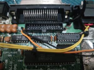
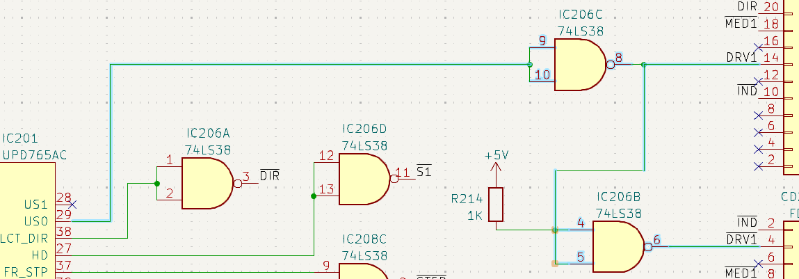
Here’s how connection from FDC looks like:
That’s the part how drive is selected, in case you want to see it all go here:
https://github.com/dr4g0nsr/cpc-schematics
As you can see here line US1 is unused/unconnected. In case it uses US1 we would have drive select logic like this:
| US1 | US0 | Drive |
|---|---|---|
| 0 | 0 | 0 |
| 0 | 1 | 1 |
| 1 | 0 | 2 |
| 1 | 1 | 3 |
So 0-3, 4 drives in total.
But let’s stick to what we have. So there is output from US0 to 74LS38 which works as inverter. Then output from that is connected to edge/centronics port 14, and to another inverter which outputs to port 4 (DRV1).
So signal from FDC UPD765AC is inverted means if signal is low it’s inverted to high and vice-versa, that inverted signal is sent to both pins, but only one of pins is active. Outputs to floppy pins is considered active (low) and inactive (high), but since one line is inverted once and second line is inverted twice, they are never active both at the same time. And this is why internal floppy is different that externally selected one. Other pins are basically sharing the same lines. When FDC is talking to one drive only that drive is sent data, other drive is ignoring it because it’s not selected.
This signal selectin is quite different from the way that it is done using PC, yet usable and compatible in a way with that signals, you can read more about it here: https://cpc.cirko.me/connect-an-internal-3-5-disk-drive-to-an-amstrad-cpc/.