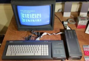
Mounting FDD port on Amstrad CPC 6128
So Amstrad decided not to make connector for the FDD port, instead they decided to solder the wire holder to board. This is, while probably cheaper, bad idea as cable will be irreplacable. This was my case as I actually tried to screw the case back but wires from FDD cable was in a way of the hole so I pierced the cable.
Finding the replacement cable is really hard but finding ordinary 3.5″ cable is easy – there were A LOT of them around.
Pierced FDD cable fix
Since I notice that cable is pierced I tought – why I don’t simply use existing connector with part of the cable that is alright and then solder another another cable on the end and have regular 34 pin cable from 26 pin (CPC)? That way you can connect regular drives instead of 3″ drive Amstrad uses. Then, if you do that, why not the cable that have 34 pin and 26 pin on both sides? That would be simply awesome!
So I did…
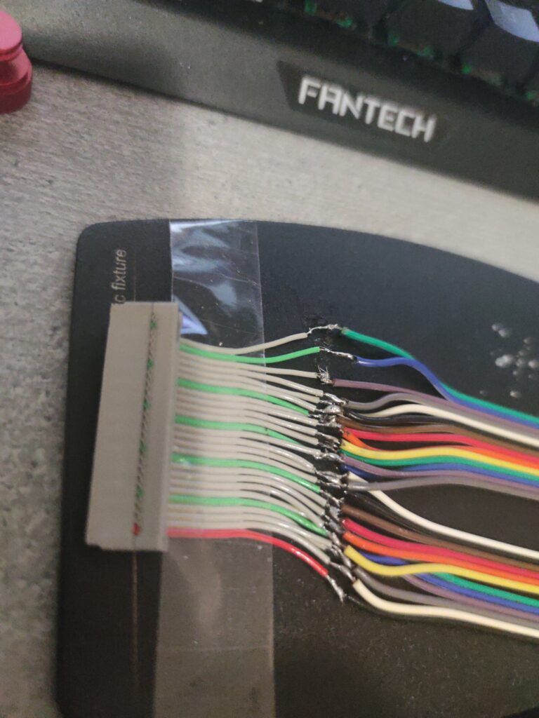
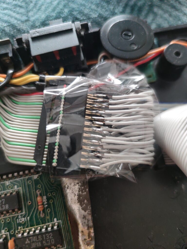
Soldering each wire out of 26 of them was a nightmare but sweet nightmare since I really expected this to work without issue! I used all-colors cable to be able to more simply identify wires by it’s pin number. Soldered cable was solid, so no trouble with soldering it to original one. Original one was real soft, I had the feeling I could cut it just by using hands. I am wondering if original is bad quality or touch of time had some impact here.
I didn’t had the tubes at that time so I used insulating tape
This time I was thinking what if I choose to replace the cable or connect different drive?
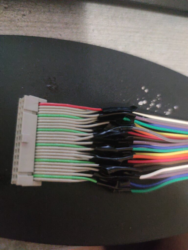
Well, at the end of this I actually made a connector on wires
This was fine, except the fact that whenever I need to open it some of the wires disconnected so I needed to solder them again. Not really well done, right?
Ok, so I was starting to think what if I solder 26 pin header directly on board instead of having this ugly hack here?
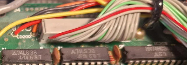
Existing FDD connector troubles
That idea leads me to first try to find 26 pin header which suprisingly wasn’t too hard to find, but desoldering the current connector was real tough, more because I messed up first time with connector when trying to move the cable so original connector got loose on the board. I used superglue to put connector back. Glue also got under connector and glued connector to the board. This makes desoldering the connector real hard (superglue was really tough one).
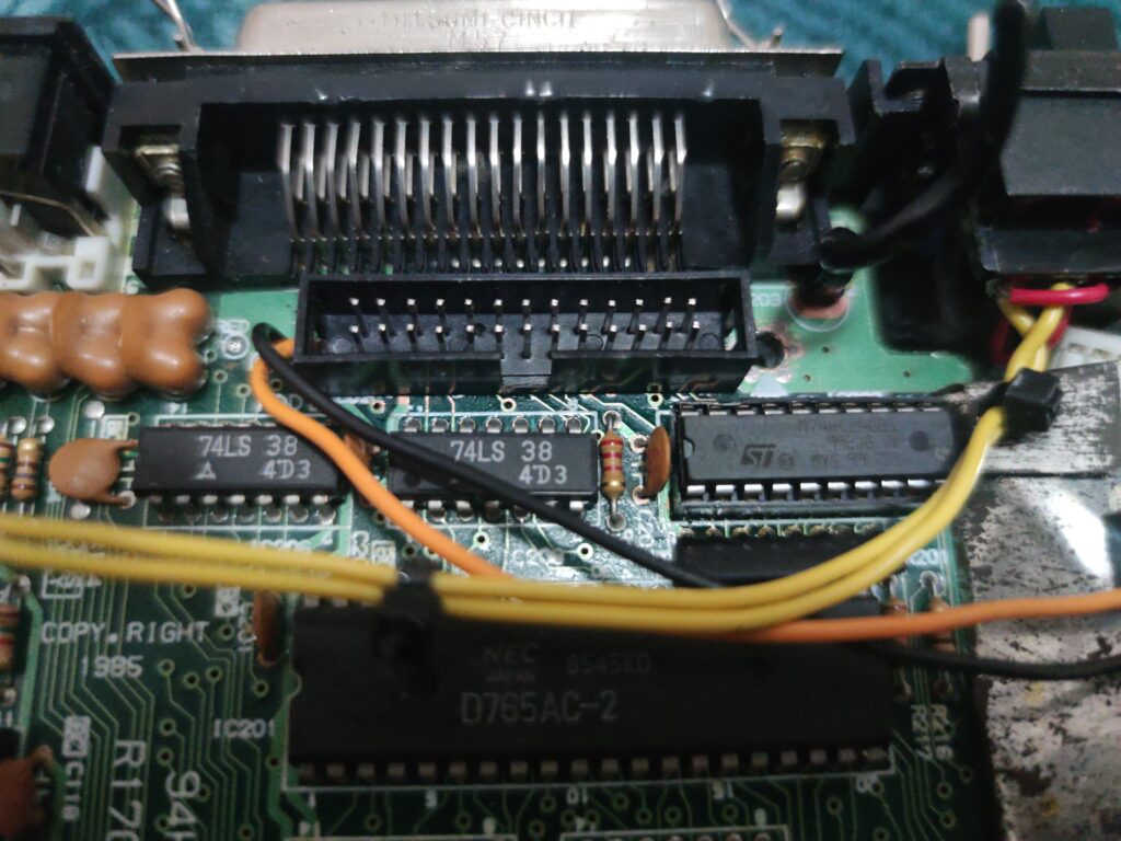
Soldering the FDD header
In the end I managed to desolder the old connector, but surprise, surprise, connector legs is FAR thinner than replacement! What a disappointment!
So what to do now? As I didn’t had any idea what to do I asked ChatGPT! It suggested me to try to thinner the header bottom using dremel. I didn’t had dremel at that time so I bought one (I will need it in the future for all kinds of things!).
So I tried to do this, not really 100% successful, but legs became slim enough to go trough the holes. This way I was able to solder them and the result is this
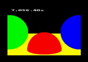
I would say job well done!
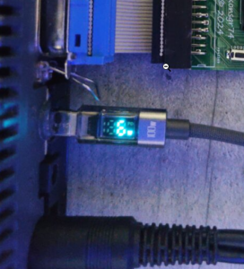
Then I connected the cable to 3.5″ gotek:
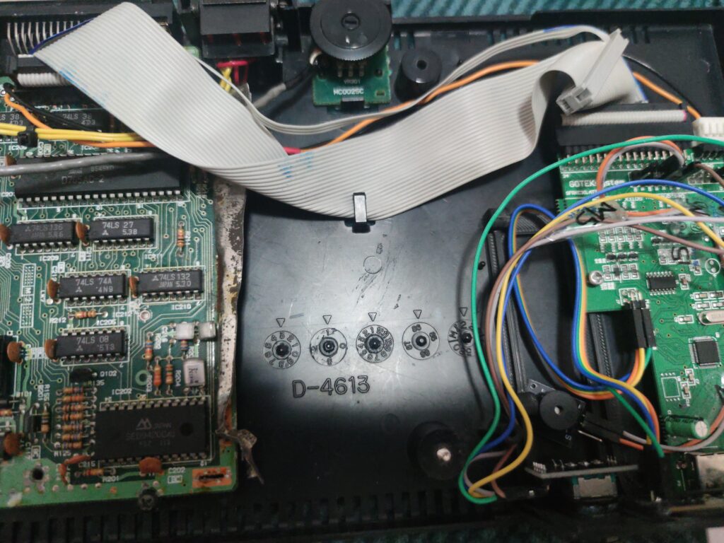
If you look closely you’ll see that I have here multiple port cable, on one site it’s 26 ping connector AND 34 pin connector, and on other site it’s the same. So you can connect 26 pin to 34 pin, 26 pin to 26 pin, 34 pin to 26 pin etc… all combinations is possible, which makes it really flexible in the terms of connecting both original drives and 3.5″ drives like gotek and floppy.